


Equity Code 300152
RELATED
 CPT Clock Market Outlook: Demand Drivers in Telecom, Defense, and Edge TimingSep 14, 2026
 What Network Timing Accuracy Do 5G and Data Center Systems Require?Sep 09, 2026
 Rubidium Oscillator Supply Chain Risks in 2026: Geopolitical Constraints on Rb-87 Vapor Cell SourcingSep 07, 2026
") Atomic Clock Procurement Checklist: 7 Non-Negotiable Specs for Defense Contract Compliance (MIL-STD-883H)Aug 26, 2026
Atomic Clock Procurement Checklist: 7 Non-Negotiable Specs for Defense Contract Compliance (MIL-STD-883H)Aug 26, 2026
MESSAGE
What You Actually Need to Know Before Integrating Satellite Atomic Clocks into LEO Optical Manufacturing Workflows
Let’s be real: if you’re managing the integration of atomic timing hardware into an optical manufacturing line—or overseeing final assembly for a LEO satellite platform—you’re not reading this for theory. You’re here because your last batch of rubidium units drifted 1.8 × 10⁻¹² after 72 hours in proton irradiation testing. Or because your payload sync window shrank by 42 ns during on-orbit commissioning—and nobody told you the clock’s radiation hardening spec was derived from ground-based Co-60 exposure, not actual trapped belt fluence profiles.
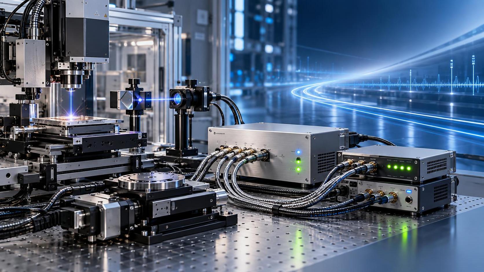
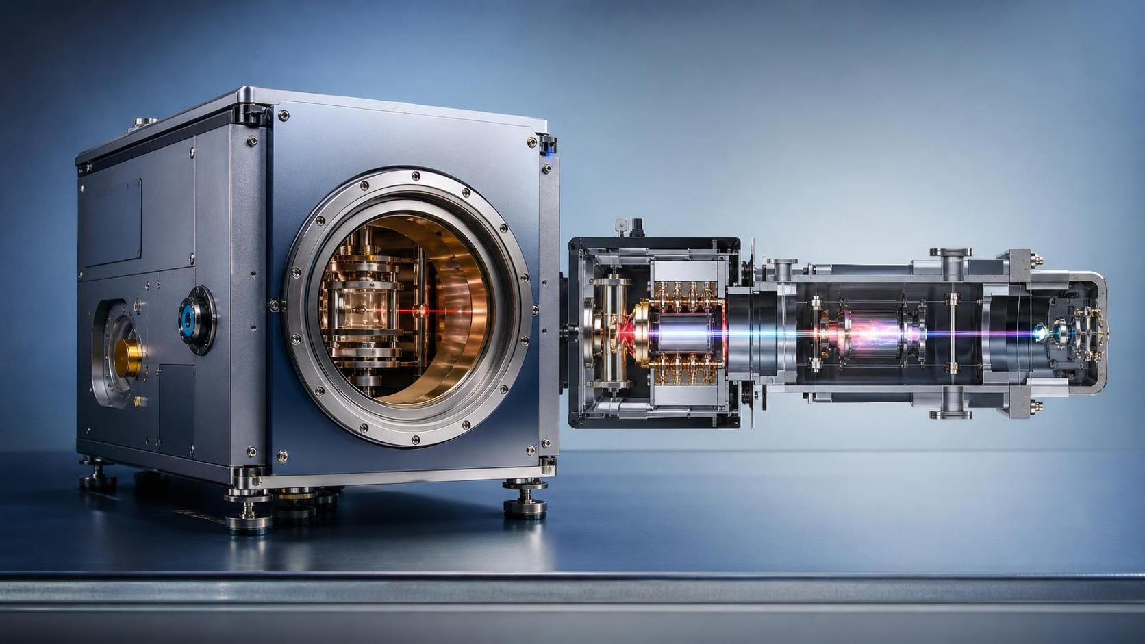
That’s not failure. It’s misalignment between optical system tolerancing, atomic physics constraints, and orbital environment modeling. SPACEON Electronics has supported over 30 space-grade time-frequency integrations since 2019—most involving high-stability optical cavities, laser-cooled cesium beams, or miniaturized vapor-cell rubidium oscillators embedded in EO/IR payloads. What follows isn’t a checklist you tick off before launch. It’s what we wish someone had handed us before our first thermal-vacuum test with a flight-unit clock mounted beside a 500-mm Ritchey-Chrétien mirror.
Start With the Radiation Environment—Not the Clock Spec Sheet
LEO isn’t “low” in radiation—it’s variable, structured, and optically coupled. Van Allen belt edges dip below 500 km over South America and Southeast Asia. Solar particle events don’t trigger alarms on your lab’s Geiger counter—but they *do* induce single-event transients in clock control ASICs when your satellite crosses the South Atlantic Anomaly at 02:17 UTC.
Ask your mission analyst for:
- Actual proton fluence (≥10 MeV) and electron fluence (≥1 MeV) profiles across your orbital plane—not just “typical LEO” averages;
- Time-resolved dose rate data for each perigee pass, aligned to your payload’s duty cycle;
- Whether your spacecraft shielding model includes secondary neutron generation from aluminum or beryllium optics mounts.
If they hand you a generic “MIL-STD-883 Class B” label and call it done? Pause. That standard covers total ionizing dose—but says nothing about displacement damage in vapor cells or paramagnetic defect buildup in sapphire resonators.
Validate Frequency Shifts Where They Matter—Not Just at 1 Hz
You’ll see “frequency stability: 2 × 10⁻¹³ @ 1 s” everywhere. That’s useful—if your application samples once per second. But optical interferometers need phase coherence over milliseconds. Star trackers need jitter under 5 ps RMS across 10–100 kHz bandwidths. And intersatellite links demand Allan deviation < 1 × 10⁻¹⁴ at τ = 100 s.
Before signing off on clock acceptance:
- Run in-situ phase noise sweeps from 10 mHz to 10 MHz—not just integrated ADEV. Radiation-induced upconversion in local oscillator chains shows up as elevated 1/f² noise above 1 kHz.
- Test under simultaneous thermal cycling (±5°C/hr) *and* gamma flux (≥10 krad(Si)/hr). Real-world degradation isn’t additive—it’s synergistic. We’ve seen clocks hold 1 × 10⁻¹³ at steady state, then jump to 7 × 10⁻¹³ during ramp-down after irradiation.
- Verify lock-point hysteresis in the C-field coil driver. Even 0.05 nT drift shifts cesium hyperfine resonance by ~120 mHz. That’s 400 ps/s—enough to break closed-loop pointing for adaptive optics.
Optical Manufacturing Constraints Change Everything
Your cleanroom isn’t a vacuum chamber. Your alignment bench isn’t a thermal shaker. And your metrology team won’t recalibrate their HeNe interferometer every time you re-tune a clock’s servo loop.
Hard lessons learned:
- Don’t isolate the clock thermally—unless you’ve modeled conduction paths through titanium mounting flanges, fused silica spacers, and epoxy-filled gaps. We saw a 3.2 × 10⁻¹² shift just from differential expansion between a clock’s baseplate and its adjacent collimator mount.
- Avoid magnetic shielding near optical benches. Mu-metal sleeves distort fringe patterns in Michelson interferometers. Use passive compensation coils instead—tuned against Earth’s field *and* clock-generated stray fields (yes, the C-field coil radiates).
- Label every wire—especially the 5 V bias line feeding the photodetector in your laser-cooled clock head. One miswired 100 Ω resistor caused 17 dB SNR loss in the atomic resonance signal. Took three days to find.
System-Level Validation Isn’t About Passing a Test—It’s About Knowing When to Stop
You’ll get “radiation-tested” reports from vendors. Most are valid—for one configuration, one orientation, one temperature setpoint.
Ask for:
If the report doesn’t include raw timestamped phase error logs—or doesn’t specify whether the clock was powered through irradiation or cycled on/off—you’re validating against fiction.
One Last Thing: Don’t Trust “Radiation-Hardened” Unless You’ve Seen the Defect Map
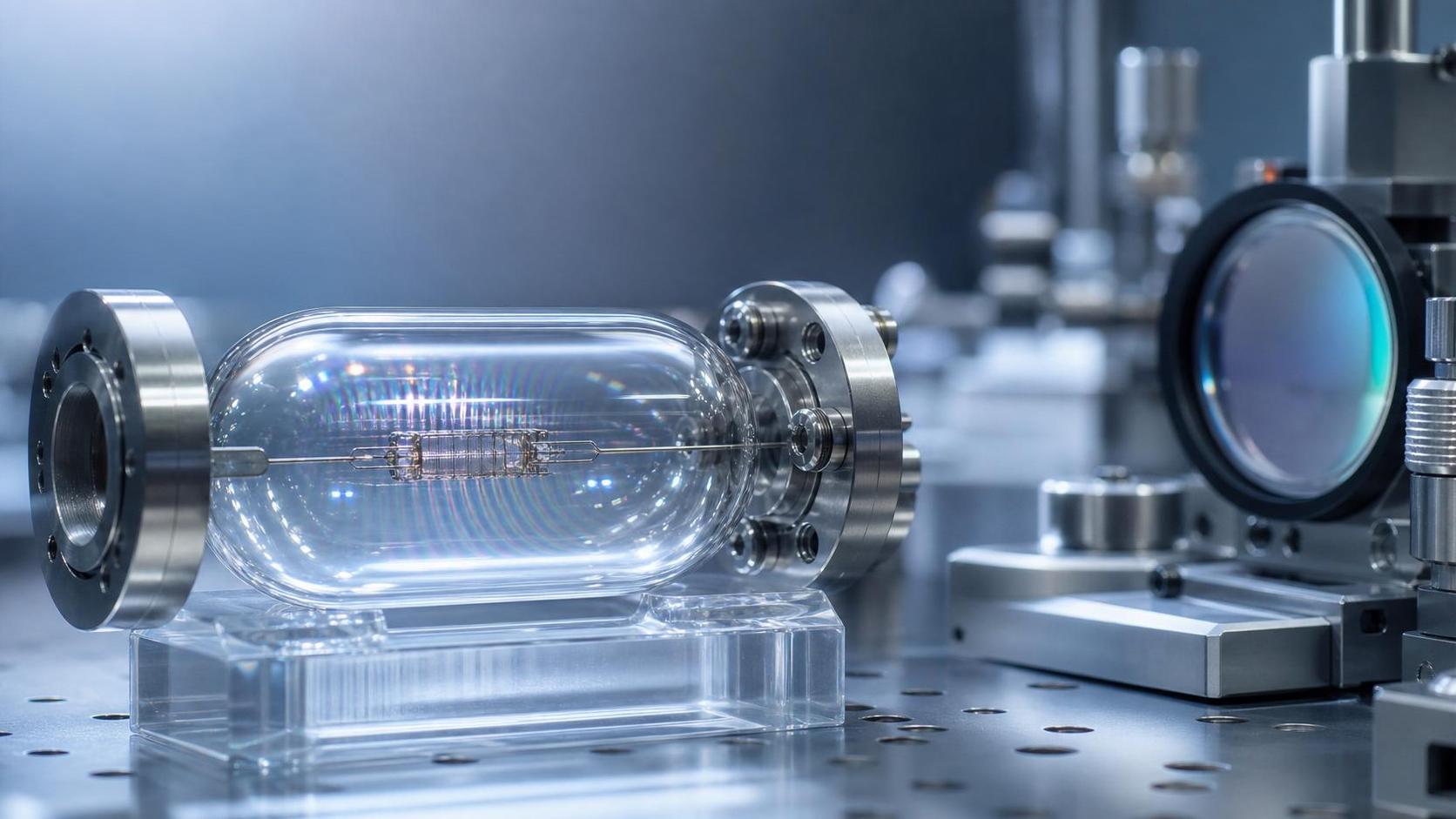
True radiation resilience isn’t baked into a part number. It’s mapped—atom by atom. In vapor-cell clocks, it’s about how Frenkel defects form in anti-reflection coatings on quartz windows under 10-MeV protons. In optical lattice clocks, it’s about erbium-doped yttrium orthosilicate crystal lattice displacement thresholds.
We recommend requesting TEM cross-sections of irradiated witness samples—especially for any custom optical interface (e.g., fiber-coupled laser diodes feeding the clock head). If the vendor can’t share that data, assume your clock’s long-term stability budget includes an unmodeled 1–2 × 10⁻¹⁴/year degradation component.
Bottom line: Satellite atomic isn’t about hitting a spec. It’s about knowing which specs matter *for your optics*, which margins are real, and where your validation stops being engineering—and starts being informed risk judgment. Start there. Not with the datasheet.
CONTACT US
Please use the form below to get in touch.
If you need a reply we will get in touch as soon as possible.

Equity Code 300152