


Equity Code 300152
RELATED
 CPT Atomic Clock Drift: Diagnosing Temperature, Light, and Magnetic Field EffectsSep 28, 2026
 CPT Atomic Clock Qualification Tests for Stability, Aging, and Environmental StressSep 22, 2026
 When a CPT Clock Is the Right Timing Source for GNSS-Denied InfrastructureSep 20, 2026
 CPT Clock Market Outlook: Demand Drivers in Telecom, Defense, and Edge TimingSep 14, 2026


MESSAGE
A CPT atomic clock that slowly moves away from its reference is not always suffering from a calibration error. In field service, drift often appears after a cabinet temperature change, an optical adjustment, replacement of a nearby power component, or relocation of the unit within a rack. The clock may still lock, report normal operating status, and produce a usable output, yet its frequency stability no longer matches the expected behavior.
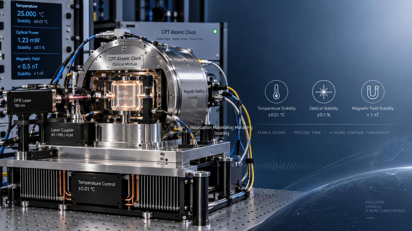
The most efficient response is to separate three environmental mechanisms before changing internal settings: temperature-dependent shifts, light-induced shifts, and magnetic-field effects. Each can move the atomic resonance, but each leaves a different pattern in the frequency record, control-loop signals, and operating conditions. Correcting the wrong parameter may temporarily hide the symptom while making long-term stability worse.
Start by confirming that the drift is real
Before opening the enclosure or adjusting the CPT lock point, verify the measurement chain. A suspected drift can originate in a comparison reference, a distribution amplifier, a cable connection, or a measurement interval that is too short to distinguish normal noise from a sustained offset.
Compare the clock output against a traceable or suitably stable reference over an interval appropriate to the observed problem. Record the environmental conditions at the same time: room temperature, enclosure temperature, supply voltage, nearby equipment activity, and any recent service work. The useful question is not only “How far did the output move?” but also “What changed at the same time?”
- A smooth shift that follows daily heating and cooling often points toward thermal sensitivity.
- A change following laser-current adjustment, optical-path service, or aging compensation may indicate a light shift.
- A step or repeatable offset when nearby equipment turns on can indicate magnetic coupling.
- Random excursions with no environmental correlation may require inspection of lock quality, electronics, power integrity, or mechanical connections before assigning the cause to the atom package.
Do not rely only on the clock’s lock indicator. A CPT atomic clock can remain locked to a distorted resonance condition. The lock status confirms that the servo is operating; it does not prove that the resonance center is free from environmental perturbation.
Temperature: more than an ambient-room issue
Temperature is often the first factor to investigate because it affects several parts of the system at once. In a vapor-cell CPT clock, cell temperature influences alkali vapor density, collision rate, optical absorption, resonance contrast, linewidth, and buffer-gas-related frequency shift. Meanwhile, temperature also changes laser diode characteristics, optical component alignment, photodetector response, microwave circuitry, and reference electronics.
A room that appears stable can still produce a problem. Airflow from cooling equipment may create local gradients across the clock enclosure. A rack-mounted unit can receive heat from a power supply below it or from an adjacent RF module. Direct sunlight, an open cabinet door, or a recently cleaned air filter can alter the thermal balance without producing a dramatic room-temperature alarm.
Symptoms that suggest a thermal mechanism
Thermal drift commonly develops gradually and may repeat with daily operating cycles. The output frequency can move in one direction as the enclosure warms after power-up, then settle after the internal thermal control reaches equilibrium. Another pattern is a frequency change that correlates with HVAC cycling, especially when the clock is located close to a vent or on the edge of a cabinet.
Look at available telemetry rather than judging only from the external output. Cell heater command, measured cell temperature, laser temperature control current, laser drive current, and internal board temperatures can reveal whether the system is actively compensating for a changing environment. A stable setpoint does not necessarily mean stable thermal conditions: large or oscillating actuator commands may show that the controller is working harder than usual.
Practical temperature checks
- Allow sufficient warm-up after power restoration, relocation, or enclosure opening. Avoid evaluating long-term drift while internal thermal loops are still settling.
- Check that air inlets, fans, heat sinks, and ventilation paths are unobstructed. Dust buildup may not cause an immediate fault, but it can raise local temperature or increase thermal cycling.
- Measure ambient temperature near the enclosure rather than at a distant room sensor. Check several positions if the installation is in a dense equipment rack.
- Review whether nearby equipment has changed duty cycle, power consumption, or installation position.
- Inspect thermal interfaces and sensor connections only according to the applicable service procedure. A loose sensor connection or degraded thermal contact can cause control instability that resembles environmental drift.
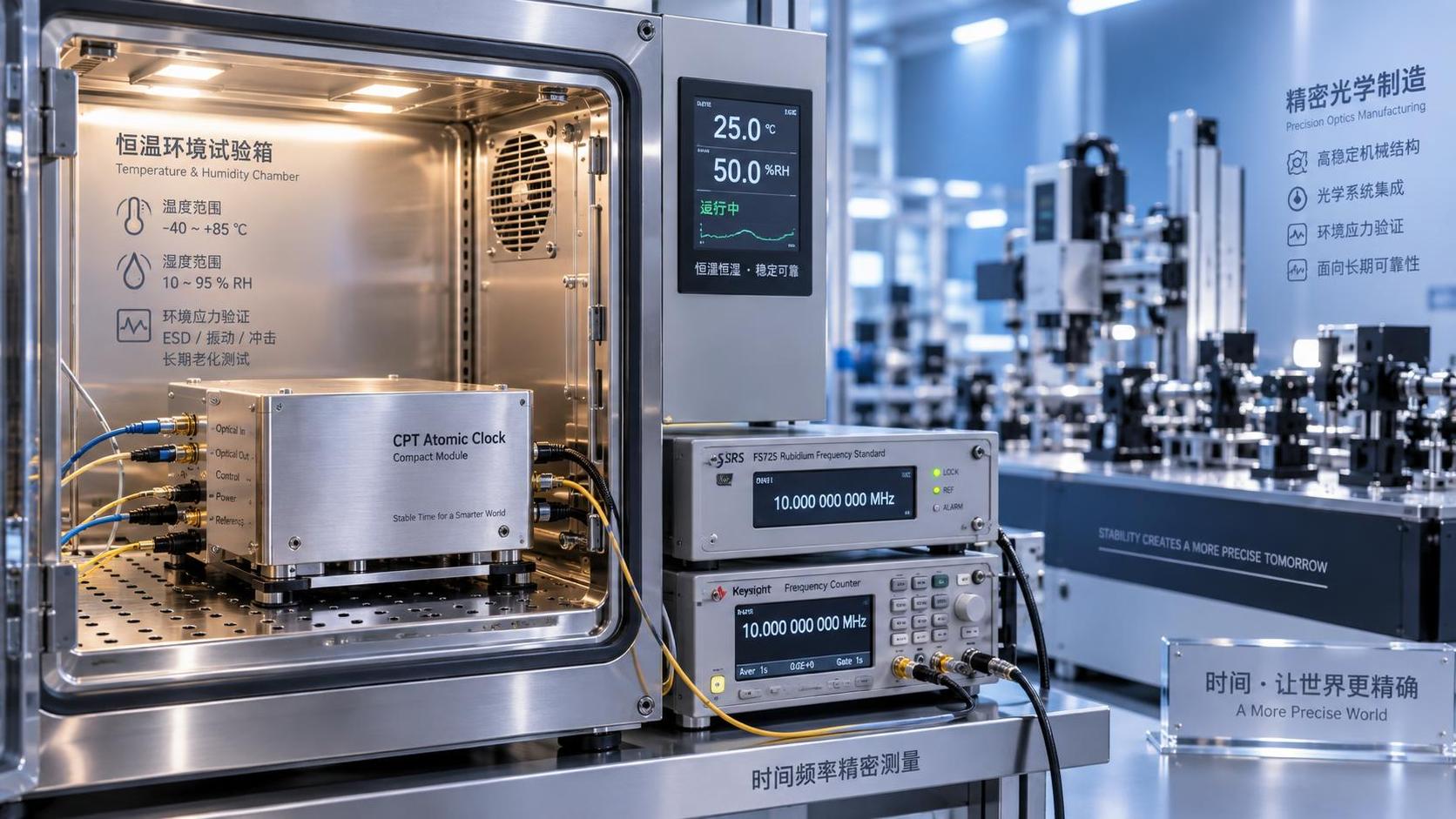
A controlled diagnostic is more informative than a random adjustment. Hold the surrounding temperature as steady as practical and observe whether the frequency slope decreases after thermal equilibrium is reached. If the drift consistently follows a known enclosure-temperature change, document the direction and magnitude of the correlation. This evidence helps distinguish cell-related sensitivity from a separate electronic reference or measurement issue.
Do not change vapor-cell heater settings merely to force the output back toward a reference. The heater setpoint is connected to atomic vapor conditions and resonance behavior. An arbitrary offset may reduce the error at one ambient condition while increasing sensitivity elsewhere.
Light shifts: when the optical lock is stable but the frequency is not
Coherent population trapping depends on carefully controlled optical fields. Changes in laser frequency, optical power, sideband balance, polarization, modulation conditions, or residual amplitude modulation can alter the observed CPT resonance. The result is a light shift: the apparent resonance center moves even though the atomic transition itself has not changed in the way the control system assumes.
This issue often appears after service involving laser drive electronics, optical connectors, fiber handling, polarization-sensitive components, or replacement of a photonic subassembly. It can also develop gradually as an emitter ages and its required current, temperature-control demand, or spectral behavior changes.
What to examine before touching optical adjustments
First determine whether the clock’s optical operating values have moved away from their established normal range. Compare present records with prior maintenance data where available. Useful observations include laser drive current, temperature-controller output, detected optical power, photodetector DC level, CPT signal contrast, error-signal shape, and servo correction values. A single optical-power reading is not enough; the same total power can produce a different atomic response if detuning or polarization has changed.
Cleaning or reconnecting optical interfaces should be done with the specified procedure and materials. Contamination can reduce transmitted power, but aggressive handling can create a larger problem through connector damage, fiber stress, or altered polarization behavior. Where the optical path is factory aligned or sealed, external correction attempts should stop at the accessible diagnostic points.
When an optical shift is suspected, make one controlled change at a time and allow the relevant loops to settle. Do not simultaneously alter laser current, temperature setpoint, microwave settings, and frequency steering. That approach destroys the correlation needed to identify the cause and may leave the unit in a condition that is difficult to restore.
Magnetic fields: small disturbances can become frequency errors
The CPT resonance is sensitive to magnetic conditions because atomic energy levels respond to magnetic fields through the Zeeman effect. Many clocks use a defined bias field to establish the intended operating condition and magnetic shielding to reduce external influence. A disturbance can therefore arise from a changing external field, a compromised shield, a magnetized nearby object, or instability in the bias-field circuit.
Magnetic problems are frequently missed because the source may not be part of the timing system. Rack fans, transformers, relays, switching power supplies, loudspeakers, motors, current-carrying cables, magnetic tool holders, and even a temporary service instrument placed against the enclosure can alter the local field. DC fields and low-frequency variations deserve attention; a field source does not need to be visibly large or continuously active to create repeatable frequency changes.
Field-related patterns worth investigating
A magnetic effect may appear as a step when a neighboring unit is energized, a periodic modulation linked to a motor or power cycle, or a persistent offset after the clock is moved. Drift that changes when a cabinet door is opened can also be meaningful if the door, latch, or mounted accessories contain magnetic material or alter the geometry around the shielded package.
Begin with a physical survey. Remove temporary magnetic tools and accessories from the immediate area. Trace high-current cables and power modules near the clock. Check whether recent rack changes placed transformers, inductors, speakers, or motors closer to the unit. Then observe the clock while suspected equipment is switched on and off in a controlled manner, provided this can be done without affecting essential service.
A portable magnetic-field meter can support the investigation, but its reading must be interpreted carefully. Measuring at the outside of a shielded enclosure does not directly reveal the field at the vapor cell. Its value lies in locating changes, comparing locations, and identifying active sources. If external measurements show a clear correlation with the frequency record, the installation environment requires correction even when the internal field cannot be measured directly.
Do not attempt to demagnetize, remove, reposition, or modify internal magnetic shields without explicit service authorization. Shielding geometry, bias-field components, and alignment can be part of the clock’s calibrated operating condition. Internal magnetic work generally requires controlled verification afterward.
A disciplined isolation sequence
When more than one cause is possible, follow the evidence rather than the most visible symptom. Temperature, optical conditions, and magnetic fields can interact. For example, a thermal change can shift laser detuning and create what looks like a pure light shift. A nearby power supply can add both heat and magnetic interference. The purpose of the sequence below is to reduce one variable at a time.
- Stabilize the comparison. Confirm the external reference, measurement configuration, and observation interval.
- Freeze the installation conditions. Keep cabinet layout, cooling state, nearby equipment status, and cable routing unchanged while collecting a baseline.
- Review internal trends. Look for changes in cell-temperature control, laser control, optical signal level, lock discriminator, and bias-related monitoring points if available.
- Test the most plausible external correlation. For a daily slope, investigate heat. For a service-related change in optical hardware, investigate light conditions. For switching-related steps, investigate magnetic sources.
- Apply one reversible correction. Improve airflow, restore approved optical configuration, or increase separation from a confirmed field source. Do not stack several changes together.
- Verify after settling. Continue comparison long enough to confirm that the correction changed the drift pattern rather than only its instantaneous offset.
Keep a maintenance record that includes initial symptom, reference used, environmental state, internal status values, changes made, and post-change behavior. For recurring drift, this record is often more valuable than a one-time frequency adjustment because it shows whether the clock is becoming more sensitive, whether a support system is unstable, or whether the installation environment has changed.
When the problem should move beyond routine site correction
Escalation is appropriate when the frequency remains abnormal after environmental conditions are controlled, when internal control loops are near their operating limits, or when the CPT signal quality has changed without an accessible external explanation. Repeated relocking, heater-control oscillation, laser-control saturation, distorted error signals, or a persistent field-related response despite removal of external sources can indicate an internal component or alignment issue.
At that stage, preserve the diagnostic evidence rather than continuing to tune the clock. Trend data, photographs of the installation layout, records of nearby equipment states, and the sequence of reversible tests can help determine whether the next action is module-level service, factory evaluation, or correction of the surrounding installation.
Reliable recovery of a CPT atomic clock depends less on making the output agree immediately and more on restoring the conditions under which the atomic resonance is being measured correctly. Temperature control, optical stability, and magnetic cleanliness should be treated as separate diagnostic paths, then verified against the same long-term reference record.
CONTACT US
Please use the form below to get in touch.
If you need a reply we will get in touch as soon as possible.

Equity Code 300152